Step 1
|
mixer
|
Step 2
|
mixer
|
Step 3
|
|
Step 4
|
|
Step 5
|
|
Step 6
|
Step 4
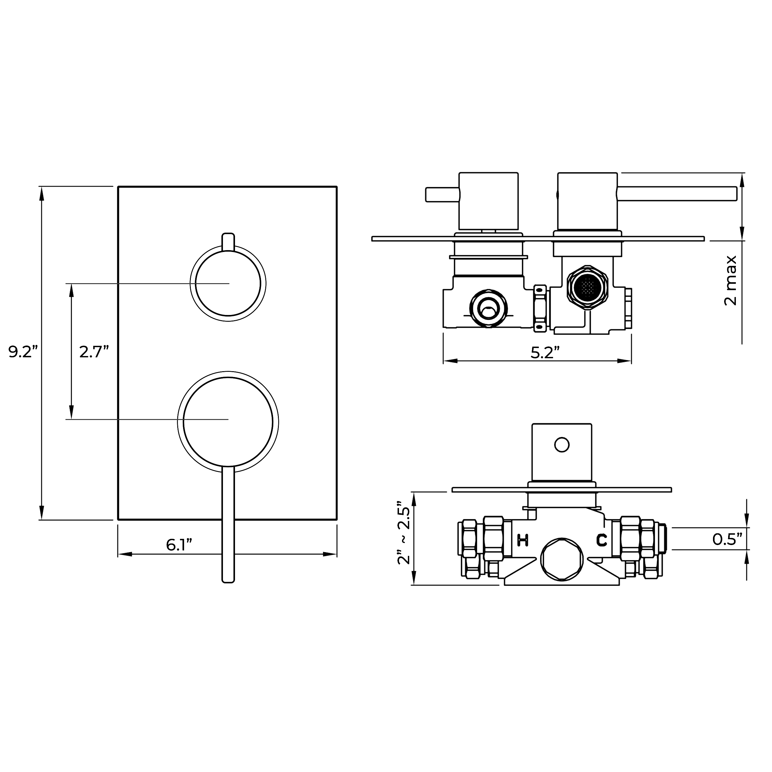
1. Attach the 15 mm hot and cold supplies (D, E) to the inlet compression fitting adaptors as shown.
2. Attach the outlet pipes for the shower (F) and the bath (G) to the respective water outlets of the shower body (A) using ½ fittings and sealing with PTFE tape. Note: (F) = Shower, (G) = Bath. If installing two showerheads and no bath outlet connect the main shower to outlet (F).
3. Test the water tightness of all inlet and outlet pipes and connections before progressing with the installation. This is best done by temporally blocking the outlet and turning the shower on.
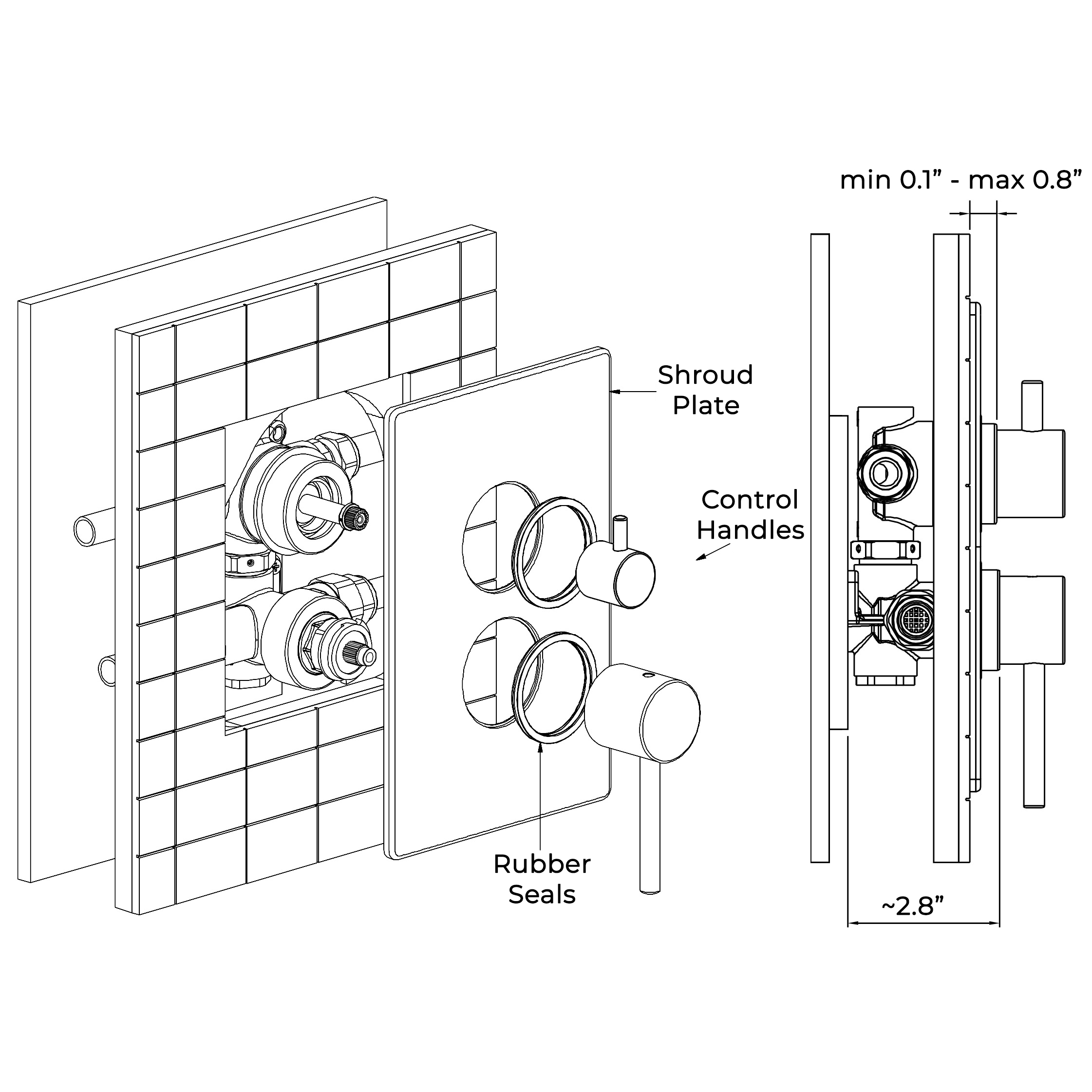
4. Make good the finished wall surface using tiles or similar, the tiles must overlap the finished shroud plate (I) by at least 15mm on each side of the plate. Note: Try to leave access to working parts for future maintenance. Ensure tile adhesive and grout are set before proceeding to next step.
5. Lubricate the inside edge of seals (K) lightly with washing liquid or similar.
6. Watchfully seal around the groove on the back side of the shroud plate (I) to prevent water ingress into the wall. Note take care not to apply a sealant to parts of the shroud plate (I) that will be displayed,
7. Carefully push the shroud plate (I) over the shower body (A) flush to the finished wall. Ensure both seals (K) are flat and flush to the outer rings of the control stems. The shroud plate (I) can be temporally taped to the tiled wall whilst the sealant dries.
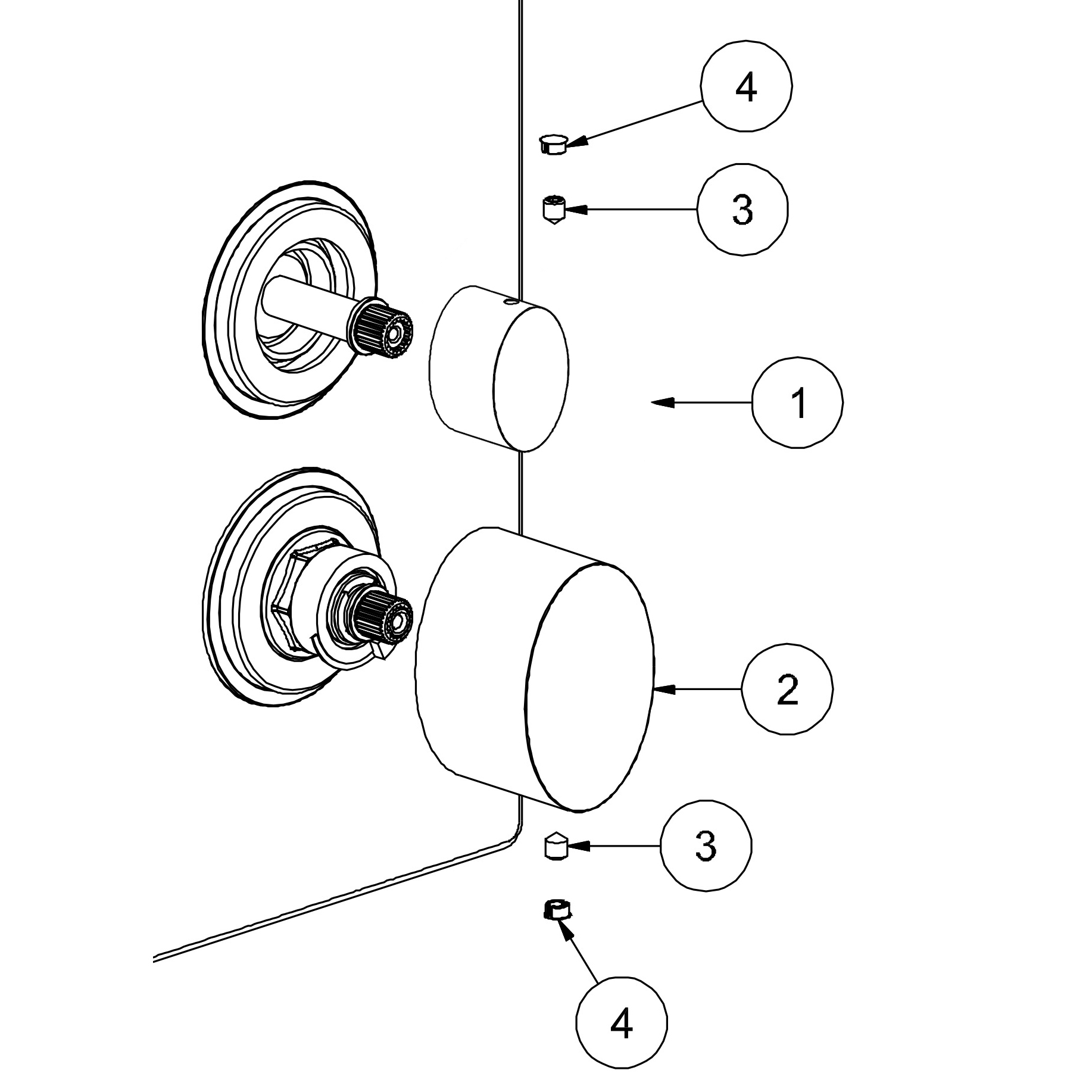
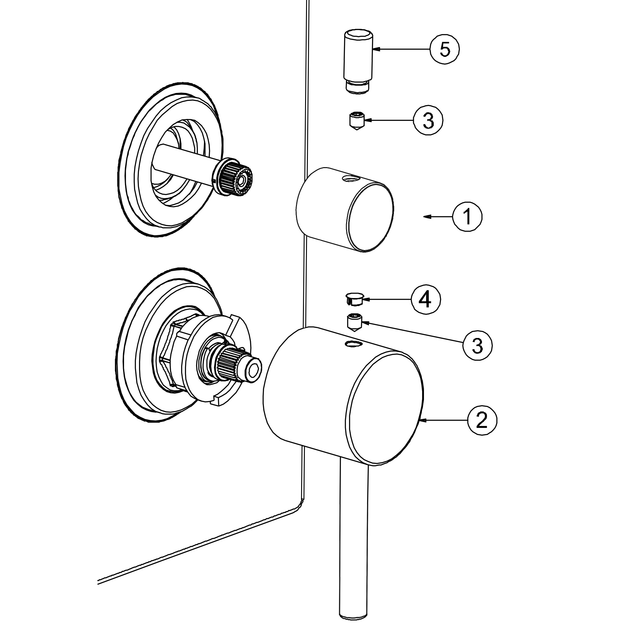
Step 5
1. Push the handle (1) onto the flow control valve. Take care to place the flow control handle (1) in alignment in the off position.
2. Tighten grub screw (3) to fix handle, make sure dust cap (4) is placed onto handle (1) as shown.
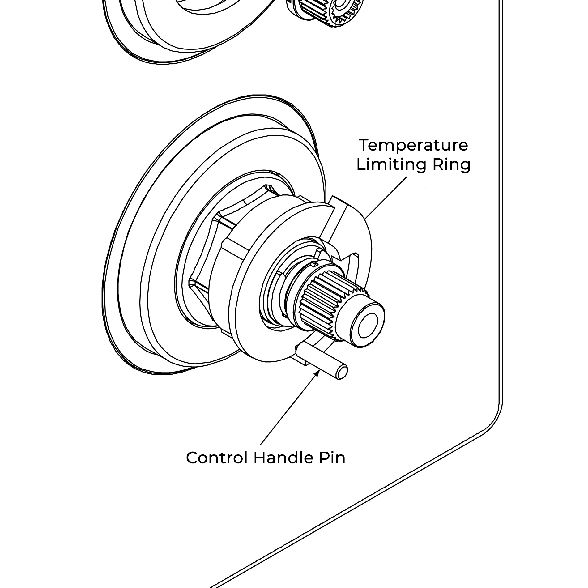
3. Push the temperature handle (2) on the valve. Ensure the control pin (A1) inside the handle (2) is not interfering with the maximum stop section of the control ring (A2).
4. Tighten grub screw (3) to fix handle, make sure dust cap (4) is placed onto handle (2) as shown.